I was clearing out an old backup drive and found a 64 KB binary I had not looked
at in twenty years: Icatel-43.17.bin, the firmware dump of an ICATEL TPCI
card payphone. TPCI stands for Telefone Público a Cartão Indutivo, the
inductive-card public payphone that TELEBRÁS standardized across Brazil. The
orelhão. I had done hardware work on a related unit back in 2004, and at some
point along the way I had pulled a firmware image and filed it away. The file
sat there, untouched, through several laptops and backup migrations, until I
opened the folder again this month.
This post is about what happened once I decided to actually reverse engineer it: disassemble the 8051 code with radare2, rebuild the state machine in Python well enough to run it, and put a small simulator on top so the thing is interactive again. Everything referenced here is in the repository:
github.com/paoloo/icatel_4317_TPCI
What was actually in the backup
The binary is small: 64 KB, the full external address space of an 8051. No
symbols, no debug information, nothing but raw code and data starting at
0x0000. That is normal for a firmware dump pulled off an EPROM or flash
chip rather than exported from a toolchain, and it means the entire project
starts from a disassembler and a lot of manual cross-checking.
I loaded it with radare2 in 8051 mode:
r2 -a 8051 -qc "e asm.arch=8051; e scr.color=0; pD 46020 @ 0x0000" Icatel-43.17.bin \
  > Icatel-43.17.r2.asm
That produced a 46,020-line linear disassembly and a function list. From
there the work is mostly archaeology: find the interrupt vector table, follow
every call, and write down only what the bytes actually prove. I kept an
[INFERENCE] tag in my notes for anything I could not verify directly
against the image, so the two categories stay separate in the final writeup.
The vector table gives the shape of the whole system immediately:
0x0000 RST  -> 0x0033   reset routine
0x0003 INT0 -> 0x41F7   keyboard (reads 0xE002)
0x000B T0   -> 0x1B9A   1.034 ms tick
0x0013 INT1 -> 0x103D   bare RETI, unused
0x001B T1   -> 0x2EF6   line-signal / charge-pulse generator
0x0023 UART -> 0x4264   supervisor / charge-pulse binary protocol
That is the whole personality of the device in six lines: a millisecond tick, a keyboard interrupt, a line-signaling timer, and a serial link back to a supervision center. Everything else in the firmware exists to serve those five entry points.
Cross-checking against my own old notes
The useful part of finding this file after twenty years is that I could
cross-reference it against paper notes I took at the time on a different but
related ICATEL unit, model 5000c/1. I had written down the self-test boot
sequence back then: EEPROM, RAM, keyboard, display, an unidentified “matriz”
stage, tariff table, card reader, modem, each one printing an OK or failure
message. icatel_4317_strings.txt has the exact same sequence, in the same
order, with matching string pairs (TESTANDO EEPROM / EEPROM OK /
FALHA EEPROM, and so on through TESTANDO MODEM). I still do not know what
the “matriz” stage tests. My best guess in 2004 was the keypad’s row/column
scan matrix, and this firmware does not settle that either.
The technician menu strings line up too: ID TECNICO, TAB.TARIFACAO,
NUMERO SERIE, TERMINAL SSTP, ATIVACAO/DESATIVACAO. Also worth
knowing: internally, in every LCD string, the firmware calls the remote
supervision center “SSTP,” never “CSA.” The TELEBRÁS standards use “CSA”
throughout, so anyone reading this against the official documentation should
expect that naming gap.
One genuine deviation from the standard turned up: TELEBRÁS 245-300-707
§8.21(i) requires the out-of-service message to read FORA DE SERVIÇO. This
firmware shows FORA DE OPERAÇÃO instead. Harmless, but a real gap between
the spec and what shipped.
The one place my old notes and this firmware genuinely disagree is the
display. I had recorded a 2x16 LCD on the 5000c/1. This firmware’s DDRAM
addressing (0x80 for line 1, 0xC0 for line 2, 40-column stride) makes the
43.17 unit’s display 2x40. Different hardware, not a contradiction, but worth
being explicit about instead of quietly reconciling it.
None of that cross-referencing would mean much on its own. What made it useful was that it gave me an independent check on the byte-level reading: when a string table built from raw disassembly matches a paper note written twenty years earlier from a different physical unit, that is a reasonable signal the reading is correct.
The parts of the firmware worth pointing at
Persistent state without a filesystem
There is no filesystem, obviously. Persistent state lives in three fixed XDATA blocks, each closed off with an additive 16-bit checksum in the last two bytes:
def block_checksum(mem: Memory, addr: int, length: int) -> int:
    """0x7D9D: plain 16-bit running sum, hi in IRAM 0x0F, lo in 0x0E."""
    total = 0
    for i in range(length):
        total += mem.xdata[addr + i]
    return total & 0xFFFF


def block_verify(mem: Memory, addr: int, length: int) -> bool:
    """0x7DAF: checksum data then compare 2-byte trailer [sum_hi][sum_lo]."""
    s = block_checksum(mem, addr, length)
    return mem.xdata[addr + length] == (s >> 8) and mem.xdata[addr + length + 1] == (s & 0xFF)
RAM is the working copy; a bit-banged I2C EEPROM (24C32/24C64 class, SCL on
P3.3, SDA on P1.7, opcodes 0xA0/0xA1) is the shadow. Every commit path
recomputes the checksum, compares it against the trailer, and only rewrites
the EEPROM block if the data is actually stale:
def commit(self, addr: int, length: int = 1) -> None:
    base = select_block(addr & 0xFF)
    if base is None:
        self.eep.write_byte(addr, self.mem.xdata[addr])       # fallback @0x7E48
        return
    end = base + {BLOCK_BASES[0]: 25, BLOCK_BASES[1]: 95, BLOCK_BASES[2]: 24}[base]
    if not block_verify(self.mem, base, end - base - 2):      # @0x7DAF
        s = block_checksum(self.mem, base, end - base - 2)
        self.mem.xdata[end - 2] = s >> 8
        self.mem.xdata[end - 1] = s & 0xFF
        self.eep.write_block(base, self.mem.xdata[base:end])  # @0x8238 whole block
That is a full write-back cache with data integrity checking, built out of plain 8051 instructions in 1996-era style, protecting card credit, tariff tables, and serial number against power loss during a phone call.
Dead code, on purpose, in the shipped image
This is the detail I liked most. Address 0x0DC9 disassembles to:
PUSH ACC
MOV A, #1
RRC A
POP ACC
RET
Rotate 1 right through carry and the carry flag comes out as 1, every
single time, regardless of what the accumulator held on entry. Several
feature-gate branches in the firmware call this routine and act on the carry
flag it returns. Since the carry is always 1, the “false” side of every one
of those conditionals is unreachable in this specific build:
@staticmethod
def stub_true() -> bool:
    """0x0DC9: PUSH ACC ; MOV A,#1 ; RRC A ; POP ACC ; RET
    RRC of A=1 shifts bit0 into C => returns C=1 UNCONDITIONALLY.
    All `LCALL 0x0DC9` conditionals compile out; the false branches
    (0x028B, 0x0417, 0x071E, ...) are dead code.
    """
    return True
My reading is that this is a single build-time flag baked in as a stub
function rather than a #define, probably so the same source tree produces
multiple product variants by swapping which routine sits at 0x0DC9. Whoever
compiled this particular image pinned the flag on. I left a note in the
Python not to “fix” those dead branches when reading the asm: they are dead
by design in this build, not a bug in my disassembly.
A pin doing two jobs
The command mailbox at XDATA 0x0708 is the value shared between the main
loop and the interrupt handlers. Writing it also mirrors the byte onto port
P1:
def write(self, val: int) -> None:           # 0x415D
    self.mem.xdata[0x0708] = val & 0xFF
    self.mem.p1 = val & 0xFF                 # MOV 0xA0,A  (port 1 mirror)
P1.7 is also the I2C SDA line. So the same physical pin is, at different moments, a general command bus and half of a serial EEPROM protocol. That only works because the EEPROM driver actively drives SDA exclusively while a transaction is in progress, and lets go the rest of the time. It is a detail you would only catch by tracing where every bit of a port gets written and noticing two unrelated call paths converge on the same pin. No schematic tells you this; it falls out of reading the code.
Metering is the actual product
The whole point of the device is that it must not give away free calls, so I
spent real time on the metering path. Timer 1 runs in external-counter mode
(TMOD=0x51), fed by charge pulses. A divide-by-6 stage turns those pulses
into 16-bit unit counters, and a call only stays connected while
credit_units is nonzero:
def tick_call_clock(self) -> None:
    """0x4DE2: advance 0x087F (sec) with mod-60 carry into 0x087E (min),
    then mirror the 3-byte clock into the session block shadow and commit."""
    self.clock_sec += 1
    if self.clock_sec >= 60:
        self.clock_sec = 0
        self.clock_min = (self.clock_min + 1) % 60
    self.mem.xdata[0x087E] = self.clock_min
    self.mem.xdata[0x087F] = self.clock_sec
    self.mem.xdata[0x003D:0x0040] = bytes([0, self.clock_min, self.clock_sec])
    if self.call_state == 2 and self.phase == 3:
        self._sec_divider = getattr(self, "_sec_divider", 0) + 1
        if self._sec_divider >= 6:
            self._sec_divider = 0
            self._burn_unit()
One unit burned every six seconds while connected, which matches the
TELEBRÁS billing method: the phone debits one card unit first, then grants
the equivalent talk time. Once the card pool is empty the phase flips to 7,
the LCD prints FAVOR DESLIGAR (“please hang up”), and the line drops.
Turning it into something runnable
Reading disassembly answers “what does this do.” It does not tell you whether your reading is internally consistent. Making it executable does, because Python either accepts the state machine or it does not.
I ended up with three files instead of one, on purpose, at different levels of fidelity:
icatel_4317_reimplementation.py is the faithful model: 792 lines, every
routine carrying the real 8051 disassembly as a docstring followed by what it
does in Python. Memory models XDATA plus the memory-mapped LCD and latch
windows; I2cEeprom reimplements the bit-banged protocol bit by bit,
including the ack-poll wait loop; Datastore reimplements the checksum and
commit logic shown above; Payphone is the actual state machine with all
five dispatch states.
simple_payphone.py is a 173-line didactic rewrite of the same observable
behavior, with the EEPROM, checksums, and banked memory stripped out, leaving
one readable state machine:
IDLE --off-hook--> DIAL_TONE --4+ digits--> CONNECTED --credit==0 / on-hook--> IDLE
Both engines carry their own self-test. Running the didactic one:
$ python3 simple_payphone.py
simple engine smoke OK
drives the whole call lifecycle headlessly: card in, off-hook, dial four digits, connect, sustain a paid call, hang up, then a second run that lets the credit hit zero and checks the phone actually drops the call instead of letting it run forever. Running the faithful engine prints the same shape of result from the other implementation:
$ python3 icatel_4317_reimplementation.py
EM CHAMADA 01:31  UNID:00
FAVOR DESLIGAR
OK: mailbox=00 tone=1 phase=4
Getting both engines to agree on the observable behavior, while disagreeing on internal fidelity, is what convinced me the state machine reading was right rather than just self-consistent.
Putting a face on it
The last piece is icatel_4317_simulator.py, a tkinter and ttk desktop app
styled after the real orelhão: steel-blue body, yellow stripe, a green 2x40
LCD, a metal keypad, a clickable card and handset. It can run either engine
(--engine full or --engine simple) so the same GUI shell drives either
the faithful reimplementation or the didactic version.
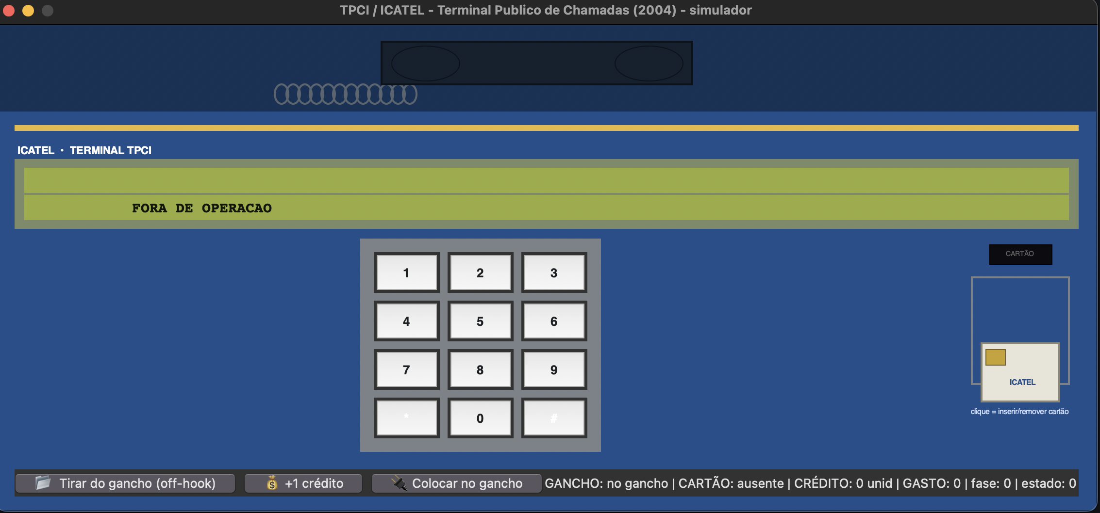
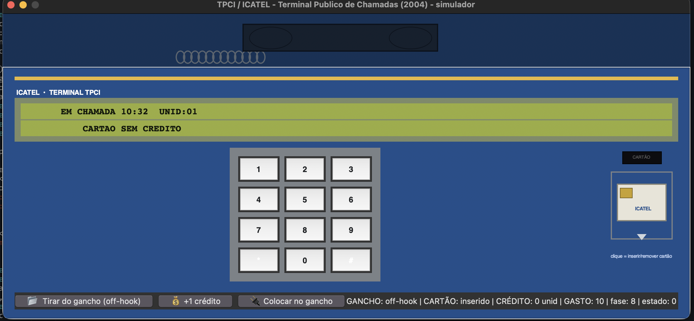
A full call in the simulator walks through the same sequence the firmware
notes describe: insert the card, go off-hook, add a unit or two, dial four
or more digits to trigger the line-seize pulse train on latch 0x8060
(4000/1300/500 wait-units, exactly as coded at 0x0617), talk while a unit
burns every six seconds, and watch FAVOR DESLIGAR appear before the credit
hits zero and the call is dropped automatically.
What is still open
Some parts did not get fully mapped. The supervisor protocol’s frame layer
is implemented and the CRC-16 checks out, but the command semantics behind
it (a 42-case dispatch table starting around 0x1189) are only partially
understood. Cycle-exact timing is modeled as tick counts, not machine
cycles. There is no SLIC or analog line-current simulation; the line status
bits are driven by the simulator UI, not by a physical model. And the
11.0592 MHz crystal frequency is an inference from the standard UART divisor,
not something the firmware states outright, though the timer-1 reload value
matching 9600 baud makes it a fairly safe one.
None of that changes the main result. A firmware image with no symbols, sitting unopened on a backup drive for twenty years, turned out to disassemble cleanly enough to rebuild as a working, self-testing Python model, cross-check against paper notes from the original hardware research, and drive an interactive simulator that reproduces the actual on-screen behavior of a device that has not been manufactured in a long time.
Full code
The full reimplementation and the tkinter simulator are large enough (792 and 318 lines) that I am linking them from the repository instead of pasting them here in full: icatel_4317_reimplementation.py and icatel_4317_simulator.py. The didactic engine is short enough to include here in full:
#!/usr/bin/env python3
"""
simple_payphone.py -- simplified, didactic implementation of the ICATEL
TPCI payphone logic, written to run under the tkinter simulator
(icatel_4317_simulator.py --engine simple).

Same observable behavior as the RE'd firmware, one readable state machine:

    IDLE ──off-hook──> DIAL_TONE ──digits──> CONNECTED ──credit==0/hang-up──> FAULT/IDLE

Contract kept from the firmware:
  * 2x40 LCD, line1 = status, line2 = dynamic info ("FORA DE OPERACAO",
    "COLOQUE CARTAO", "DISQUE: 1234", timer, "FAVOR DESLIGAR").
  * Off-hook without card -> "COLOQUE CARTAO", with card -> dial tone state.
  * Digits buffer (11 max, '*' clears) mirrors XDATA 0x0783-0x078D.
  * 4+ digits -> CONNECTED, per-second timer (mod-60, like 0x4DE2/0x789C),
    each credit unit (metering pulse / T1 pin) decrements available units.
  * Out of credit -> "Favor desligar" + phase 7 -> hang-up, state 0.
  * Card removal mid-call -> immediate fault phase, hang-up.
"""

from __future__ import annotations
import time

LCD_COLS = 40

# phases mirror firmware 0x0013 values where possible
P_IDLE, P_WAITING, P_CONNECTED, P_DIALING, P_HANGUP, P_FAULT = 0, 2, 3, 4, 7, 8

class PayphoneSim:
    def __init__(self) -> None:
        # state
        self.state = 0            # 0 idle, 1 tone/dialing, 2 connected, 3 ended
        self.phase = P_IDLE       # 0x0013-ish
        self.card = False
        self.hook_off = False     # False = on hook
        self.units = 0            # available credit units
        self.digits = ""          # dialed buffer (max 11)
        self.connected_for = 0    # seconds in call
        self.msg_timer = 0        # ticks left for transient messages
        self.transient = ""       # transient line2 message
        self.tone = 0             # 0 none, 1 dial tone, 2 in-call
        # LCD shadow (0x0708-0x0747 in firmware)
        self._l1 = " " * LCD_COLS
        self._l2 = " " * LCD_COLS

    # ---------------------------------------------------------- hardware --
    def hook(self, off: bool) -> None:
        self.hook_off = off
        if not off:                          # on hook during call -> hang up
            if self.state in (1, 2):
                self._end_call("FAVOR DESLIGAR")

    def card_inserted(self, present: bool) -> None:
        was, self.card = self.card, present
        if not present and self.state == 2:
            self._end_call("CARTAO RETIRADO")     # firmware: 0x2F.4 path
        elif present and not was and self.state == 0:
            self._show("COLOQUE CARTAO OK")       # brief acknowledge

    def credit_unit(self) -> None:
        """One metering pulse (T1 pin in firmware TMOD=0x51 counter mode)."""
        self.units += 1
        if self.state == 2:
            self._render()

    def keypress(self, ch: str) -> None:
        if self.state != 1:
            return
        if ch == "*":                             # correction key clears buffer
            self.digits = ""
        elif ch.isdigit() and len(self.digits) < 11:
            self.digits += ch
        self._render()

    # ------------------------------------------------------------- engine --
    def tick(self) -> None:
        """Called at simulator rate (~20 Hz); 1 tick = 1 loop iteration."""
        # -- state machine first: transient messages only delay display, ----
        # -- never the off-hook / dial / connect transitions.
        if self.hook_off and self.card and self.state == 0:
            # firmware 0x01DC->0x020A: state=1, phases 4/4, tone profile 1
            self.state, self.phase, self.tone = 1, P_DIALING, 1
            self._render()
        elif self.hook_off and not self.card and self.state == 0 \
                and not self.transient:
            # firmware 0x0433: "COLOQUE CARTAO" display block
            self._show("COLOQUE CARTAO", ticks=40)
            self.phase = P_WAITING
        elif self.state == 1 and len(self.digits) >= 4:
            # firmware 0x0617: seize line, state=2, phases 3/3, tone 2
            self.state, self.phase, self.tone = 2, P_CONNECTED, 2
            self.connected_for = 0
            self.units = max(self.units, 1)       # first unit granted
            self._render()
        elif self.state == 2:
            self.connected_for += 1
            cost = self.connected_for // 6        # ~1 unit per 6 s
            if cost >= self.units:
                self._end_call("FAVOR DESLIGAR")
            else:
                self._render()
        # transient countdown last: display-only, never blocks transitions
        if self.msg_timer > 0:
            self.msg_timer -= 1
            if self.msg_timer == 0:
                self.transient = ""
                self._render()

    # -------------------------------------------------------------- misc --
    def _end_call(self, reason: str) -> None:
        self.state, self.phase, self.tone = 0, P_HANGUP, 0
        self.digits = ""
        self._show(reason + (" -> RETIRE O CARTAO" if self.card else ""),
                   ticks=60)
        if not self.card:
            self.phase = P_IDLE

    def _show(self, msg: str, ticks: int = 20) -> None:
        self.transient = msg
        self.msg_timer = ticks
        self._render()

    # --------------------------------------------------------------- LCD ---
    def _render(self) -> None:
        if self.transient:
            self._l1 = " " * LCD_COLS
            self._l2 = self.transient.center(LCD_COLS)[:LCD_COLS]
            return
        if self.state == 0:
            self._l1 = "   SEMINT 93 / ICATEL".ljust(LCD_COLS)[:LCD_COLS]
            self._l2 = "FORA DE OPERACAO".center(LCD_COLS)[:LCD_COLS]
        elif self.state == 1:
            self._l1 = "DISQUE (ate 11 digitos):"
            self._l2 = self.digits.ljust(LCD_COLS)[:LCD_COLS]
        elif self.state == 2:
            mm, ss = self.connected_for // 60, self.connected_for % 60
            self._l1 = f"EM CHAMADA  {mm:02d}:{ss:02d}  UNID:{self.units}"
            self._l2 = self.digits.ljust(LCD_COLS)[:LCD_COLS]
        else:
            self._l1, self._l2 = " " * LCD_COLS, " " * LCD_COLS

    def lcd_line1(self) -> str: return self._l1
    def lcd_line2(self) -> str: return self._l2


if __name__ == "__main__":
    # headless logic smoke test
    p = PayphoneSim()
    p.card_inserted(True); p.hook(True); p.tick()
    assert p.state == 1, p.state
    for ch in "1234": p.keypress(ch)
    p.tick()
    assert p.state == 2, p.state
    for _ in range(10): p.credit_unit()      # pay 10 units (card pulses)
    for _ in range(50): p.tick()
    assert p.state == 2 and p.connected_for >= 50
    p.hook(False)
    assert p.state == 0
    # out-of-credit path: default 1 unit -> drop after ~6 s (phase 7)
    p2 = PayphoneSim()
    p2.card_inserted(True); p2.hook(True); p2.tick()
    for ch in "1234":
        p2.keypress(ch)
    p2.tick()                                 # connect
    dropped = False
    for _ in range(12):
        p2.tick()
        if p2.state == 0 and p2.phase == 7 and p2.msg_timer > 0:
            dropped = True
            break
    assert dropped, (p2.state, p2.phase, p2.transient)
    print("simple engine smoke OK")